In this beginning module students will learn the first Arduino programming project, "Hello World." Then students will progress to multiple LED light configurations while becoming familiar with the programming language and basic electronic principles.
Arduino - Project 1 - 1 LED Light "Hello WOrld"
Follow the directions to program the Arduino Uno Microcontroller to flash one LED light on and off. Have your Arduino out and ready with the USB cord. Connect the USB cord to your laptop.
Please remember the terms like; pin, led pin, High, Low, digital write and delay.
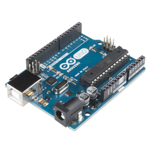
Pin - referes to the pin that you will plug in to on the board. Notice in the picture that the Arduino has pins numbered 0-13 on one side. These are the digital pins. For project 1, we will be using pin 13.
Void Loop - means that you are telling the Arduino to loop or repeat the instructions over and over again.
digital write - is telling the Arduino to send a signal to a certain pin.
High - means you are telling the Arduino that the signal will be ON.
Low - means that you are telling the Arduino that the signal will be OFF.
Delay - means that you are telling the Arduino how long it should stay ON or OFF. (Wait) (Pause)
**
1. Follow the wiring schematic on slide 1. Place an LED light with the shorter leg in pin hole labeled GND and longer leg in 13. GND means ground. (see slide 2)
2. Open the Arduino IDE (Integrated Development Environment) software and copy the code from slide 2.
3. Be sure to check your code for mistakes. You can also run a debug check by clicking on the checkmark symbol.
4. If you do not get any orange error messages, then it will be ok to upload the code to your Arduino.
5. First make sure that you go to tools menu and select Board and then Arduino Uno.
6. Plug in the USB cord to both the Arduino Uno and your computer.
7. Next in tools, go to port and select the choice that contains USB.
8. Finally, click on the Arrow button. It should upload and you should see the LED blinking.
Please remember the terms like; pin, led pin, High, Low, digital write and delay.
Pin - referes to the pin that you will plug in to on the board. Notice in the picture that the Arduino has pins numbered 0-13 on one side. These are the digital pins. For project 1, we will be using pin 13.
Void Loop - means that you are telling the Arduino to loop or repeat the instructions over and over again.
digital write - is telling the Arduino to send a signal to a certain pin.
High - means you are telling the Arduino that the signal will be ON.
Low - means that you are telling the Arduino that the signal will be OFF.
Delay - means that you are telling the Arduino how long it should stay ON or OFF. (Wait) (Pause)
**
1. Follow the wiring schematic on slide 1. Place an LED light with the shorter leg in pin hole labeled GND and longer leg in 13. GND means ground. (see slide 2)
2. Open the Arduino IDE (Integrated Development Environment) software and copy the code from slide 2.
3. Be sure to check your code for mistakes. You can also run a debug check by clicking on the checkmark symbol.
4. If you do not get any orange error messages, then it will be ok to upload the code to your Arduino.
5. First make sure that you go to tools menu and select Board and then Arduino Uno.
6. Plug in the USB cord to both the Arduino Uno and your computer.
7. Next in tools, go to port and select the choice that contains USB.
8. Finally, click on the Arrow button. It should upload and you should see the LED blinking.
|
LED Bulb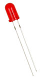
|
Arduino IDE Software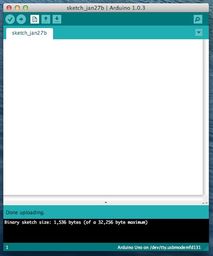
Download at www.arduino.cc
|
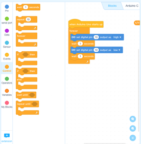
For beginners who may be familiar with Scratch or Tickle App. Try mBlock.
Download at www.mBlock.cc |

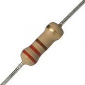
Resistors
|
A resistor is a passive two-terminal electrical component that implements electrical resistance as a circuit element.
Resistors act to reduce current flow, and, at the same time, act to lower voltage levels within circuits. Resistors are used to reduce the flow of current or electrons to an electrical component in order to reduce the chance of that component burning out due to excessive current/voltage. |
Breadboard

A breadboard is a construction base for prototyping of electronics. Because the solderless breadboard does not require soldering, it is reusable. This makes it easy to use for creating temporary prototypes and experimenting with circuit design.
Arduino - Project 2 - 1 LED w/resistor & Breadboard
Here is a different setup. An LED usually uses 2-3 volts. When connecting an LED directly to the pin without a resistor it receives a full 5 volts. This can lead to the LED eventually burning out. So we use a resistor to reduce the power going to the LED. This activity will also get you started using the breadboard, jumper wires and resistors.
1. Wire up the Arduino according to the diagram (sometimes called Fritzing schematic).
2. Look at the project code on slide 2 and read it carefully. Understand what pins are going to be used. It is very similar to project 1.
3. The only difference will be in the pin selected.
4. Upload the program to the Arduino board and see if it works. Stop the program when you know it worked correctly.
5. Move on to project 3.
Arduino - Project 3 - 3 LED Light Display
Arduino LED Project 4 - Robot Eye
Arduino LED Project 5 - Push Button (Introducing the "If Else" statement.)
In this project you will learn that the "if else" statement will let you do conditional commands. If you meet one condition then another condition will occur. This is similar to the "if then" statements of other programming or coding languages. Here you will tell the Arduino, if the button is pushed, else (then) turn on the light.
Arduino LED Project 6 - LED Button Delay
Arduino Project 7 - RGB LED Light (red-green-blue)
Arduino Project 8 - Mood Detector with RGB LED w/TMP36 temperature sensor
Follow the wiring directions below to create a Mood Detector. Then copy the code and upload to the Arduino.
Later add additional colors by duplicating an "else if " statement several times and changing the color for each. (refer to chart for colors). Notice how the inequality or comparison operators <= (less than or equal to) show that anything below a specific number triggers the color change.
Be sure to calibrate the temperature that you want each change to occur by observing how the temperature changes in the serial monitor. Be sure to open the serial monitor located in the tools menu so you can see the temperature changes as you touch the sensor. Change the settings if you need to. Then make a key or chart that describes color and mood.
Extend: You could extend this by adding beeps after each color change. By adding a variation of buzzer project #1 you could add different amounts of beeps each time a color change occurs with the temperature increase.
Engineering & Design Challenge: Create an enclosure or case that would hide the Arduino, Breadboard and Wires, but show the RGB LED and the Temp36 sensor.
Project #9 LED with Potentiometer (Fading)
In this project you will learn how to attach a Potentiometer (knob) to the projects and use it to brighten or dim the LED light. Also called Fading.
Christmas Tree & Wreath
Use mBlock to code your Arduino. You will need to make a Christmas Tree or Wreath out of Cardboard and paint it. Then poke the LED lights through the holes.
STEM
Engineering Design Process

|
|
Math

|
Units of measurement
Unit conversion 1 second = 1000 milliseconds If it takes 30 seconds to microwave an egg, how many microseconds would that be? 1000 milliseconds X 30 seconds = 30,000 milliseconds 1 second 1 1 |
Science

|
Electromagnetism: conductors, insulators, polarity, Ohm's law.
Light - Color - Time |
Technology

|
Microcontrollers
Coding/Programming CAD Drafting software |
